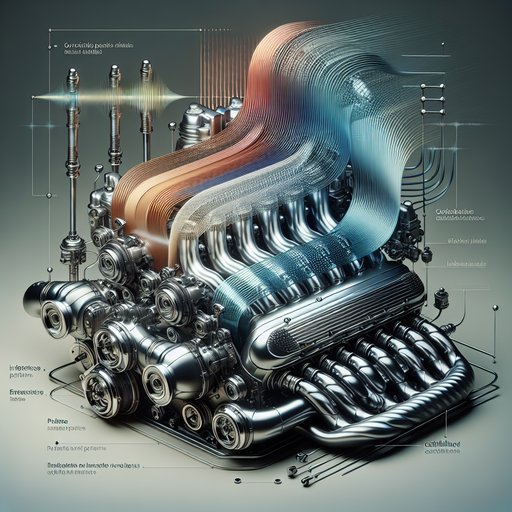
Intake systems can do more than deliver air—they can time pressure waves to boost torque and use side-branch volumes to cancel boom. Runner length exploits quarter-wave reflections so a positive pressure wave arrives near intake valve closing, improving cylinder filling. Resonators target narrow frequency bands tied to engine orders, flattening cabin drone without adding backpressure. With a few equations and practical rules-of-thumb, you can pick lengths and volumes that land the torque bump where you want it and knock down NVH hotspots, all while keeping flow losses low and packaging realistic.
The basic problem is that naturally aspirated and lightly boosted engines lose filling efficiency as speed rises, and intake pulsations can create audible boom at fixed cruise. The core idea uses acoustics in two ways: first, a tuned runner length returns a compression wave to the valve just before it closes to push a bit more air in; second, a side-branch resonator is tuned to the dominant boom frequency to attenuate intake duct pressure fluctuations. Runner tuning hinges on wave travel time. When the valve opens, a rarefaction wave travels up the runner and reflects off the plenum as a compression wave.
If that positive wave arrives near IVC (typically 40–80° ABDC), it raises instantaneous pressure at the valve and increases volumetric efficiency. A practical rule-of-thumb is: L_eff ≈ a × θ_target / (12 × RPM × m) where a is speed of sound in the runner gas (m/s), θ_target is crank angle from IVO to desired arrival (deg, usually 90–120), RPM is engine speed at desired torque peak, and m is the odd harmonic (1, 3, 5...). Use a ≈ sqrt(γRT); at 60–80°C intake air, a ≈ 360–380 m/s. L_eff includes port, runner, and end corrections.
Mechanism and example: open-end reflections at the plenum invert phase, turning the initial rarefaction into a returning compression. Travel time is t = 2L_eff/a; you align t to the desired crank-angle window within the 4‑stroke cycle (2 rev = 720° = 120/RPM s). Example: 2.0 L I4, target peak torque at 4000 rpm, θ_target = 100°, a = 365 m/s, m = 3 (third harmonic for packaging). L_eff ≈ 365×100/(12×4000×3) ≈ 0.28 m.
Adding port length and bellmouth end correction (≈0.6–0.8×runner radius) often yields a physical runner of 300–380 mm. Expect about 3–8% BMEP gain centered near the tuned speed, with taper and plenum sizing shaping bandwidth. Constraints and trade-offs: shorter runners push the torque bump to higher RPM; longer runners favor midrange. The amplitude depends on wave strength (runner/plenum area ratio and valve event timing) and dissipates with throttling and charge heating.
Plenum volume V_pl to total displacement is commonly 1.5–2.5× to buffer cylinder-to-cylinder coupling and broaden response. Runner CSA should keep peak Mach ≲0.6; high velocity boosts wave intensity but risks pressure loss. On turbo engines, post-compressor volume and intercoolers damp pulses, so runner tuning still helps low–mid RPM but with smaller gains. Variable-length systems switch between, say, ≈350 mm and ≈200 mm to widen the plateau.
Drone reduction uses resonators. Two common types: - Helmholtz (side branch cavity): f_H = (a/(2π)) × sqrt(A/(V × L_eff)), where A is neck area, V is cavity volume, L_eff is neck effective length (add end corrections ≈1.7r at each unflanged end). These are compact and narrowband. Example: target 120 Hz intake boom on a 4‑cyl (boom often aligns with overall intake event rate (N_cyl/2)×RPM/60: at 2000 rpm, 2×33.3 ≈ 67 Hz; higher orders and duct modes can land near 120–150 Hz).
Choose neck d = 25 mm (A ≈ 4.9×10^-4 m^2) and L_eff = 0.08 m; solve V = A/[((2πf_H)/a)^2 × L_eff] ≈ 1.4×10^-3 m^3 ≈ 1.4 L. - Quarter-wave branch: f_QW ≈ a/(4L_qw) for the 1st mode; highly effective but longer. For 120 Hz at a = 360 m/s, L_qw ≈ 0.75 m; coiling or using higher odd modes (L ≈ L_qw/3, /5) can help packaging at the cost of bandwidth. Practical NVH notes: place resonators near the source (plenum or upstream duct) and on low-velocity regions to minimize flow loss.
Target the dominant engine order(s): for a 4‑cyl 4‑stroke, intake events sum to 2nd order; inline‑6 to 3rd order; V8 to 4th. Temperature shifts f by ~0.5% per 3°C because a ∝ sqrt(T); add 5–10% margin or use multiple smaller resonators staggered in frequency. Perforated-necks add resistance, widening the notch but reducing depth. Ensure water drains and account for MAF sensor placement to avoid metering bias.
Implications: Proper runner length yields a noticeable midrange torque rise without fuelling changes, improving BSFC 1–3% at common cruise/load by enabling lower throttle and taller gears. Resonators cut 5–15 dB at the targeted boom with negligible restriction when A_neck is small relative to duct area. Reliability is high—no moving parts—but packaging and heat drive cost and variance. Emissions are neutral; smoother intake pressure can stabilize idle and transient fueling.
Real-world drivability improves as the torque curve fills in and cabin booming at 1500–2500 rpm is suppressed without resorting to aggressive active noise control.


